Getting data signals into and out of an RF shielded test enclosure presents a fundamental contradiction. The enclosure is designed to block RF signals from crossing its shielded walls — that is its entire purpose. But to test the device inside, you need to pass stimulus signals and measurement data across that same barrier. The challenge is that data signals, at their core, are RF signals. A USB 3.0 data stream at 5 Gbps is an RF signal at 5 GHz. A 10GBASE-T Ethernet connection uses signaling that falls squarely within the WiFi and cellular frequency bands. If you filter out everything above 1 GHz, you will block the interference — but you will also destroy your data.
This paper explains the three filtering approaches used to solve this problem, when each one applies, and why selecting the right one matters for your test results.
The Fundamental Tradeoff
Every filtered data connection is a compromise between two competing goals: pass the data signal with minimal degradation, and attenuate RF interference as much as possible. At low data speeds, this tradeoff is easy — the data frequencies are far below the interfering RF frequencies, and a simple filter can separate the two cleanly. As data speeds increase and begin to overlap with the interference frequencies, the tradeoff becomes increasingly difficult, requiring more sophisticated filtering techniques.
JRE Test addresses this with three distinct filtering approaches, each suited to a different region of the data speed spectrum.
Approach 1: Capacitive Feedthrough Filtering
Best for: RS-232, audio, thermocouples, simple control lines, DC power sense lines, and other signals below approximately 100 Mbps
The simplest and most economical filtering method uses feedthrough capacitors mounted inside a standard DB-style connector (DB9, DB15, or DB25). Each pin passes through a capacitor connected from the pin to ground — the connector housing, which is bonded to the enclosure wall. At low frequencies (where your data lives), the capacitor's impedance is very high and the data passes through essentially unimpeded. At RF frequencies (where the interference lives), the capacitor's impedance drops to near zero and the interference is shorted to ground.
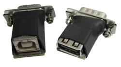
Simple PCB adapters can connect DB-9 pins to USB, 3.5 mm audio, RJ-style, or other connector types.
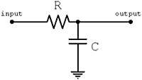
The math behind this is straightforward. The impedance of a capacitor at any given frequency is determined by its capacitive reactance:
![]()
Where Xc is capacitive reactance in ohms, f is frequency in hertz, and C is capacitance in farads.
Example 1 — RS-232 serial data: 9600-baud RS-232 produces a data stream at approximately 19.2 kHz. A 1000 pF feedthrough capacitor presents an impedance of about 8,300 ohms at this frequency:
Xc = 1 / (2π × 19,200 × 1000 × 10⁻¹²) ≈ 8,300 Ω
Since a typical RS-232 driver has a source impedance on the order of a few hundred ohms, the 8,300-ohm shunt capacitor causes negligible loading — the data passes through with no meaningful attenuation or distortion. Meanwhile, at 2.4 GHz (WiFi), that same 1000 pF capacitor presents an impedance of only 0.066 ohms — essentially a dead short to ground for the interference. This is an ideal outcome: data passes, interference is killed.
Example 2 — Analog video: Now consider a higher-frequency signal. Analog video has frequency components up to about 4 MHz and typically uses 75-ohm source impedance. The same 1000 pF capacitor at 4 MHz presents an impedance of only 39.8 ohms:
Xc = 1 / (2π × 4,000,000 × 1000 × 10⁻¹²) ≈ 39.8 Ω
Combined with the 75-ohm source impedance, this forms a voltage divider that passes only about one-third of the original signal at 4 MHz — and even less at higher video frequency components. The result is a severely rolled-off response that will visibly degrade the video. At lower video frequencies the attenuation is less severe, but the uneven frequency response produces a blurry, degraded image.
The lesson is clear: capacitive filtering works beautifully when the data frequencies are far below the RF interference frequencies, but it breaks down as data speeds increase. The higher the data speed, the closer your data gets to the interference in frequency, and the harder it becomes for a simple capacitor to tell the two apart.
Choosing the right capacitance value:
We offer DB connectors in three capacitance values:
1000 pF — maximum RF filtering, suitable for data rates up to approximately 10 Mbps. Best for RS-232, audio, slow control lines, and similar low-speed signals.
100 pF — moderate RF filtering, suitable for data rates up to approximately 100 Mbps. Use when 1000 pF causes unacceptable data degradation but you still need meaningful RF attenuation.
The general rule: use the largest capacitance your data speed will tolerate. More capacitance means better RF filtering.
The Pi-Filter Variant: Terminal Strips
For DC power lines, thermocouple leads, and other low-frequency connections, our terminal strip mounted feedthrough filters use a Pi-style topology — two capacitors (2500 pF each) with a series inductor between them. This three-element filter provides 60 to 75 dB of attenuation at VHF and above, significantly outperforming a single feedthrough capacitor. The Pi-filter is the standard approach for power and low-speed control connections where data speed is not a concern and maximum RF filtering is desired. These terminal strips are rated at 250 VAC / 100 VDC at up to 20 amps.
Approach 2: Low-Pass Filtering
Best for: USB 2.0 (480 Mbps), Ethernet 10/100/1000 (up to 1 Gbps)
When data speeds reach hundreds of megabits per second, simple capacitive filtering causes unacceptable data degradation — as the video example above demonstrated. But at these speeds, there is still a usable frequency gap between the data and the most common interference sources. USB 2.0 data tops out at 480 Mbps, while WiFi starts at 2.4 GHz and cellular signals are above 700 MHz. A well-designed low-pass filter can be placed between these two frequency ranges, passing the data while rejecting the interference.
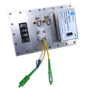
The JRE USB 2-1 filtered interface does exactly this. It passes all USB 2.0 data unimpeded while filtering frequencies above 700 MHz by over 60 dB. The connection is fully conductive — allowing compliant USB enumeration, handshaking, and power delivery — something that fiber optic alternatives cannot provide.
The JRE LAN-1 takes the same approach for Ethernet. It passes 10/100/1000BASE-T data (up to 1 Gbps) with a flat response below 480 MHz, while providing over 80 dB attenuation above 1 GHz. This cleanly separates the Ethernet data from WiFi, cellular, and other common interference sources.
Low-pass filtering works well as long as the data frequencies stay below the interference frequencies. But what happens when they don't?
The Problem: When Data Speeds Enter RF Territory
Consider USB 3.0 SuperSpeed at 5 Gbps. The signaling frequency falls squarely in the range of WiFi, Bluetooth, and many cellular bands. A low-pass filter that blocks 2.4 GHz WiFi will also block USB 3.0 data — they occupy the same frequency range. The same problem exists for USB-C SuperSpeed (5–20 Gbps), Thunderbolt (up to 40 Gbps), 10GBASE-T Ethernet (signaling within the WiFi/cellular spectrum), and HDMI at higher resolutions.
This is the central challenge of modern high-speed data filtering: the data you want and the interference you don't want are at the same frequencies. Capacitive filtering cannot solve it. Low-pass filtering cannot solve it. A fundamentally different approach is needed.
Approach 3: Patented Signal Phasing Technology
Best for: USB 3.0 (5 Gbps), USB-C (5–40 Gbps), Thunderbolt (up to 40 Gbps), 10GBASE-T Ethernet (10 Gbps), HDMI 1.4+
JRE Test developed and patented (US 10,374,572B2 and US 10,644,670) a fundamentally different filtering approach that does not rely on frequency separation at all. Instead, it exploits a physical property difference between the data signals and the interference: the data is differential, and the interference is common mode.
Here is what that means. High-speed data interfaces like USB 3.0, 10GBASE-T Ethernet, and HDMI transmit data as balanced differential signals — two conductors carrying equal and opposite voltages. The data information is encoded in the difference between the two conductors. Any signal that appears equally on both conductors (common mode) is not data — it is interference picked up from the environment.
JRE's patented signal phasing technique exploits this distinction. The filter uses a topology that passes differential signals (the data) while attenuating common-mode signals (the interference). Since RF interference picked up by cables and conductors manifests as common mode, the filter can reject it even though it occupies the exact same frequency range as the data. There is no upper frequency limit on this approach — the filter does not use low-pass filtering at all.
This is the technology inside our USB 3-1, USB-C, LAN-10G, and HDMI filtered interfaces.
Cable Quality Matters
Because the patented filters discriminate between differential data and common-mode interference, they achieve maximum isolation when the data signals are as perfectly balanced as possible. In practice, this means that cable quality, shielding, and length matter more with these filters than with simple capacitive or low-pass designs.
Use good-quality, properly shielded cables. Keep cable lengths as short as practical — the USB-C filter, for example, electrically "looks like" approximately 1 to 1.5 meters of additional cable in the signal path, so total cable length including the filter should be kept to roughly 1.5 meters for passive cables at the highest speeds. For speeds above 10 Gbps (Thunderbolt, USB4), an active cable on the external side can compensate for the additional path loss.
If the connected devices and cables are not well-balanced — for example, when using a 10GBASE-T filter with lower-speed 10/100/1000 Ethernet equipment that was not designed for the tight balance requirements of 10G signaling — the filter's ability to discriminate between data and interference will be reduced. In that case, the LAN-1 low-pass filter will actually provide better isolation at those lower speeds than the LAN-10G, because the low-pass approach does not depend on signal balance.
For much more detail on USB-C and Thunderbolt cable length, speed, and active cable considerations, see our whitepaper: USB-3 and USB-C Special Considerations.
The Universal Filtered Interface: UFI-1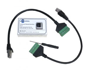
Not every signal fits neatly into USB, Ethernet, or HDMI. Many test scenarios involve a mix of thermocouples, CAN bus, RS-485, automotive Ethernet (100/1000BASE-T1), FlexRay, LVDS, audio (TRS/XLR), 20 mA current loop, or other specialized protocols. The JRE UFI-1 Universal Filtered Interface provides 8 independent filtered lines with screw terminal connections, allowing you to connect virtually any signal type without needing a purpose-built interface for each one. The filtering is designed to pass data signals while rejecting RF interference — suitable for most control, sensor, and lower-speed data applications.
Fiber Optic: The Nuclear Option
When absolute maximum isolation is required and no conducted electrical connection can be tolerated, fiber optic feedthroughs provide the ultimate solution. Since fiber is non-conductive, there is zero conducted RF path across the enclosure wall — the only signal that passes is light.
JRE Test offers the JRE FPT fiber pass-through (up to 5 cables, rated to 6 GHz enclosure isolation) and the Fiberplex WGF-6 precision connector (up to 6 cables, greater than 60 dB isolation at 25 GHz, greater than 100 dB below 10 GHz, rated to 28 GHz).
The tradeoff with fiber is that it breaks the conductive connection — USB enumeration, handshaking, power delivery, and any protocol that requires a galvanic connection will not work over fiber. For applications where this is acceptable (or where media converters can be used on both sides), fiber provides isolation that no electrical filter can match.
Selecting the Right Approach: A Quick Guide
Here is how to choose:
- Your signal is below 10 Mbps (RS-232, audio, thermocouples, slow control lines): Use a filtered DB connector with the highest capacitance your signal will tolerate — start with 1000 pF.
- Your signal is DC power or low-frequency AC power: Use a Pi-filter terminal strip or the PEM-1 filtered power entry module.
- Your signal is USB 2.0: Use the JRE USB 2-1 (single) or USB 2-2 (dual).
- Your signal is Ethernet 10/100/1000: Use the JRE LAN-1 (single) or LAN-2 (dual).
- Your signal is USB 3.0 SuperSpeed: Use the JRE USB 3-1 (single) or USB 3-2 (dual).
- Your signal is USB-C or Thunderbolt: Use the JRE USB-C.
- Your signal is 10GBASE-T Ethernet: Use the JRE LAN-10G (single) or LAN10G-2 (dual). Confirm your equipment is 10GBASE-T (RJ-45 copper), not 10GBASE-R (SFP+/fiber) — these are fundamentally different and the filter is designed exclusively for 10GBASE-T.
- Your signal is HDMI: Use the JRE HDMI-1 (single) or HDMI-2 (dual).
- Your signal is a mix of thermocouples, CAN, RS-485, automotive Ethernet, or other specialized protocols: Use the JRE UFI-1.
- You need maximum isolation with zero electrical connection: Use fiber optic feedthroughs.
- You need both Ethernet and USB on one interface: We offer combination filters — LAN-USB 2, LAN-USB 3, LAN10G-USB 2, and LAN10G-USB 3.
Browse the complete selection of I/O interfaces on our website.
Further Reading
For an overview of RF shielded test enclosures and why isolation matters: Taking the Mystery out of RF Wireless Testing.
For guidance on selecting an enclosure and configuring your I/O: How to Select and Configure an RF Shielded Test Enclosure.
For USB-C and Thunderbolt cable length, speed, and active cable guidance: USB-3 and USB-C Special Considerations.
For how multiple I/O filters interact and affect overall system isolation: The Effect of Adding Multiple I/O Filters to a Test Enclosure.If you are unsure which filtering approach is right for your application, contact us — we configure these systems every day and can advise quickly.