 More and more devices today have RF wireless circuitry inside, whether it be something obvious like a cell phone or computer laptop to something as innocuous as a new car key fob. These wireless devices communicate over the open airways and their operation depends upon careful consideration and design of their operating frequency, power level, signaling format and other technical issues. Since these devices are wireless, design and testing presents new challenges to the engineer, especially to one not accustomed to having signals propagating without any physical means of connection!
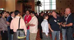 Imagine yourself in a large meeting room with hundreds of people milling about, many groups conversing loudly, while some holding more personal quiet conversations. The human ear and brain, being an incredible signal processing system can, in many cases, pick out your conversational partner from amid this room of talk, but how many times have you not perfectly understood the conversation or asked someone to repeat themselves?
This low frequency analog (!) to RF wireless communication is especially appropriate to characterizing and testing of your wireless device. How do you know that what you are testing is coming from what you are generating? Let's dissect that point: in your lab, can you be sure that the device is 'hearing' only your test signal? Are you measuring the device itself or perhaps the device from the bench across the lab? Or the microwave oven warming up someone's lunch, or the Bluetooth headset left 'on' in the desk drawer, or the wifi router in the lab, or a cell phone 'handshake/enumeration', or the... well, you get the point, unless we can reliably isolate all other potential signals, we cannot ever expect to test with any veracity!
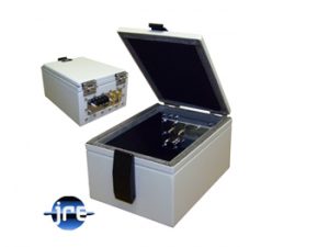
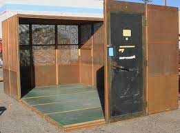 Historically, screen rooms, also known as Faraday Cages or rooms, were used to provide a clean RF environment for testing, these rooms being quite large enclosing not only the device but the entire lab bench and all equipment, including operator! In the past, when RF wireless was not so ubiquitous, these large expensive screen rooms were a reasonable solution to testing, but now as virtually every enterprise finds itself involved in RF, there has to be a better way. Enter the benchtop RF test enclosure. For the vast majority of RF tests, the benchtop RF shielded test enclosure is a perfect solution. Its small size, vast array of I/O connector options and tight RF isolation allows one to test their device in a silent, clean RF environment, assuring that the signals being used and presented are from the device and nothing else.
Now that we are assured of having a sterile RF environment, how do we get our test signals into and out of the shielded test chamber or enclosure? Simple RF bulkhead style connectors are ideal for penetrating the enclosure barrier (while this is just the metal enclosure wall, defining it as such is really quite enlightening - it truly is a barrier!). These connectors allow the pass through of any RF test signals, but what about any other signals such as data lines, power lines, or control signals? Each conductor passing through the barrier wall must be suitably filtered or the shielding integrity of the enclosure will be compromised. Careful selection of the filtering is dependent upon many variables such as data speed, power current requirements, frequency of device under test as well as simple mechanical issues such as cable length, connectors used and desired placement.
 Signals within the RF test chamber need to be dampened to reduce RF reflections and standing waves which can impact device operation. Think of a room where every surface is hard, with no curtains, furniture or acoustic ceiling tiles. Now add in a group of school children, a few TV sets or video games and imagine the noise and confusion. The sounds reverberate throughout the room, bouncing off the walls, creating quite a cacophony. Now picture the same room with carpets, proper ceilings, and soft furniture. Even though the kids are still creating the ruckus, the room becomes quieter. This is the effect that we are shooting for with RF signal absorbent enclosure lining. The hard, and RF reflective, walls are deadened and absorb the reflections, allowing the device within to see a more real-life representation of RF free space. JRE Test uses industry leading RF attenuating materials to provide such an environment.
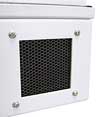 What if you have a device which generates a significant amount of heat and would cook inside an enclosure? We are faced with the need for allowing air to pass freely into and out of the enclosure but still need to stop any RF signals from passing. While simple metallic screening can be used (indeed, competitive enclosures use common window screen exclusively) JRE uses high performance mil-spec rated honeycomb hexagonal cell filters which permit smooth airflow through the filter while effectively stopping any RF penetration.
Many tests require serial data connectivity whether it be USB, RS-232 or Ethernet. Interfacing these data formats requires thoughtful consideration of the data speeds and RF Frequency of the device under test. Here's the problem: we wish to allow serial data (which is nothing more than a form of modulated RF) into and out of the enclosure while still stopping RF signals from entering or exiting the box. If our data signal is fairly slow, we can use a simple capacitive filtered connector such as DB-9 style serial connector. 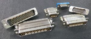 Capacitance values are available ranging from 1000 pf to as small as 10 pf. While this capacitance will load the data lines, there can be a trade-off regarding acceptable serial data attenuation/distortion and acceptable RF filtering attenuation. For example, 9600 baud RS-232 serial data results in a serial data stream of approximately 19.2 KHz, so hanging a 1000 pf capacitor across one of the data lines would in effect load the line with 8.3 K ohms to ground. (capacitive reactance is equal to: 1/(6.28(19.2 x 10^3)(1000 x 10^-12)). In most cases this extra loading will not result in any appreciable attenuation or distortion of the 9600 baud data. We can use this same sort of reasoning when we consider other serial data interface filtering, making a reasonable tradeoff between amount of capacitance and data speed. In general we should use the most capacitance possible while still maintaining an acceptable amount of loading on the data lines, this provides the maximum amount of RF filtering.
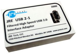 The previous paragraph outlined the basic idea behind RF filtering of data lines in general terms, but what if we have high speed data, speeds that are actually in the high RF frequency range such as USB 2.0? JRE Test developed a filtered high speed USB2.0 JRE USB2-1 Filtered USB 2.0 filterfilter for this purpose, it will filter all frequencies above 1 GHz by over 60 db while allowing all USB 2.0 data to pass unimpeded. The connection is totally conductive allowing fully compliant USB enumeration and handshaking, something not possible when using other interfaces such as fiber optic. While the cost of this interface is more than a simple filtered DB style connector, it is almost $1000 cheaper than fiber optic interfacing, which was the only other alternative.
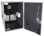
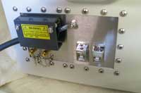 What should one look for in selecting an RF shielded test chamber? To be truly useful, any piece of equipment should be easy and intuitive to operate, if it's a hassle to operate and set up, you'll probably not use it as much as needed. What can make the enclosure easy to use? After all its only a box, right? A wide variety of input/output connectors is probably the highest on the usage list. Having the correct connector already installed and mounted makes the job easier, but it also avoids the potential problems of RF leakage and loss due to the use of many coaxial adapters and cables. Almost every JRE Test enclosure uses a standardized I/O connector plate that is interchangeable with other enclosures in the JRE test product line.
 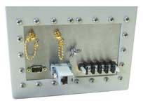 These panels are plenty roomy and have an area of almost 20 square inches, allowing a wide variety of connectors to be located on one panel, hopefully covering every conceivable I/O need, but if testing requires, you may change the panel for another. These plates allow you to simply unbolt a panel and change it out with another, thus a group of low cost panels can be configured for almost any sort of testing and be kept handy for any sort of test.
 Another overlooked issue is the maintenance of the enclosure, since it is a mechanical device, it is subject to wear, particularly on the mating RF gasketed surfaces.
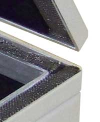
 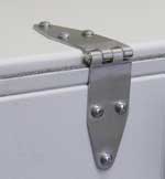 JRE Test utilizes rugged knitted mesh stainless steel or Monel gaskets on a long life Neoprene core. These gaskets have a long life on many tens of thousands of depressions, but are easily changed out when needed, and at low cost. Oversized hinges contribute to long life as well as better shielding effectiveness due to less free travel and bearing 'slop'. Cover latches are also important, as wear over time compresses the shielding gaskets, many JRE enclosures feature adjustable latches where one is able to easily adjust the latch to seat the cover more firmly and tightly.
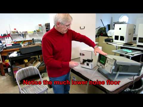
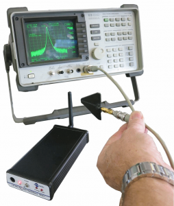 How does one know if the enclosure is still shielding effectively? JRE Test is the only enclosure manufacturer that produces a RF test chamber validation and test kit, the JRE HPSS-1. Comprising of a high power 2.45 GHz synthesized signal source in a Li-Ion battery powered extruded aluminum box with dipole antenna, this source is placed within the enclosure to be tested. A high gain yagi antenna is then used to 'sniff' around the exterior of the enclosure looking for RF leakage. The antenna can be used with a receiver or more commonly a spectrum analyzer to see the radiated signal from the test box within. Using this simple setup, one can easily measure RF isolation greater than 110 db. Watch the video below to learn how to measure the isolation using the HPSS-1 click here:
Clearly, we are testing in exciting times, more wireless means more potential - potential markets, profits and interference. JRE Test can help the designer, production test engineer and operator to make reliable measurements you can count on!